The concrete wall panel element allows you to easily model, analyze, and design concrete walls for in plane
Note:
Here we will explain the concrete-specific inputs and design considerations. For general wall panel information, see the Wall Panels topic. For concrete wall design rule information, see the Concrete Wall - Design Rules topic. For concrete wall results interpretation, see the Concrete Wall Results topic.
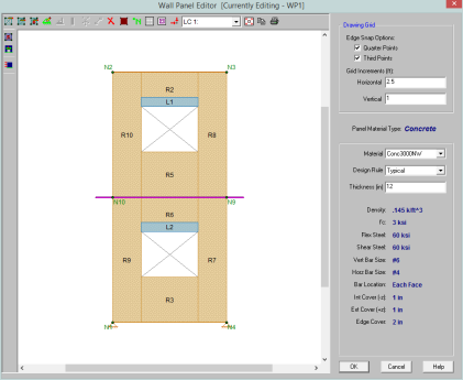
Double-click on the wall from the model view to open the Wall Panel Editor. This dialog displays input information such as Material and Design Rule, as well as gives viewing options for Region and reinforcement display (after solution). Within this dialog you also have control over the application of continuous boundary conditions.
Concrete wall panels have the following view controls:
 Toggle Region display allows you to turn the display of regions on or off.
 Toggle Lintel display allows you to turn the display of lintels on or off.
 Toggle Reinforcement display allows you to turn the display of reinforcement on or off after you have solved your model.
Concrete walls depend on Regions for results presentation. The program automatically creates these regions at solution time. If you have a wall panel with no
Within each region, the program will optimize the spacing of bars for strength, spacing and minimum reinforcement considerations of the wall.
From within the Wall Panel Editor, you have the option of creating rectangular regions within the concrete wall panel. Regions are used to define reinforcement in different parts of the wall. Each region will be assigned a uniform reinforcement, which may be different than the reinforcement in other parts of the same wall (unless you are using Group Story option from Wall Design Rules).
If no regions have been drawn on a wall then they will be automatically generated when a solution is performed. To automatically generate regions prior to running a solution, click the
To manually draw regions, select the 
The program will design the reinforcement spacing for you. For this design reinforcement spacing, rho, and strength requirements are considered for design. If specific reinforcement is defined in the Wall Design Rules spreadsheet then it may be possible for the reinforcement design to not meet code requirements.
Sections 25.2 and Chapter 11 have provisions regarding min/max spacing, required reinforcement ratios, and proper proportioning of wall reinforcement. If your wall does not meet a code requirement the program will give a red warning message in the detail report.
Section 25.2 (General Reinforcement Requirements)
The minimum spacing requirements from Section 25.2.1 are considered for design.
Chapter 11 (Wall Reinforcement Detailing)
The maximum spacing requirements from section 11.7.2.1 and 11.7.3.1 are considered for design.
Note:
The minimum spacing requirements of Section 11.6.1 are also considered for design. Additionally, the thickness requirement from Section 11.7.2.3 as well as the proportioning and cover checks in that section are also considered.
The program will consider the reinforcement requirements of Section 11.6.2 if the Vu exceeds 0.5*ϕ*Vc.
The program will design the reinforcement spacing for you. For this design reinforcement spacing, rho, and strength requirements are considered for design. If specific reinforcement is defined in the Wall Design Rules spreadsheet then it may be possible for the reinforcement design to not meet code requirements.
Sections 7.6, 14.3 and 11.9 all have provisions regarding min/max spacing, required reinforcement ratios, and proper proportioning of wall reinforcement. If your wall does not meet a code requirement the program will then give you a red warning message in the detail report.
Section 7.6 (General Reinforcement Requirements)
The minimum spacing requirements from 7.6.1 and the maximum spacing requirements from section 7.6.5 are considered for design.
Section 14.3 (Wall Reinforcement Requirements)
The minimum spacing requirements of Sections 14.3.2 and 14.3.3 and maximum spacing requirements of 14.3.5 are also considered for design. Additionally, the thickness requirement from Section 14.3.4 as well as the proportioning and cover checks of 14.3.4 are also considered.
Section 11.9.8 and 11.9.9 (Shear Reinforcement Requirements for Walls)
The program will consider the reinforcement requirements of Section 11.9.9 if the Vu exceeds 0.5*ϕ*Vc (per Section 11.9.8).
The program will design the reinforcement spacing for you. For this design reinforcement spacing, rho, and strength requirements are considered for design. If specific reinforcement is defined in the Wall Design Rules spreadsheet then it may be possible for the reinforcement design to not meet code requirements.
Clause 14.1.7.1 and 14.1.8 have provisions regarding wall geometry, min/max spacing, required reinforcement ratios, and proper proportioning of wall reinforcement. If your wall does not meet a code requirement the program will then give you a red warning message in the detail report.
Clause 14.1.7.1 (General Wall Geometry Requirements)
The thickness of the walls shall be not less than the smaller of lw / 25 or hu / 25, but not less than 150 mm.
Clause 14.1.8 (Wall Reinforcement Requirements)
The program considers the provisions for reinforcement diameter (14.1.8.2), number of layers (14.1.8.3), max spacing of reinforcement (14.1.8.4), and min reinforcement ratio (14.1.8.5 & 14.1.8.6).
The reinforcement is designed to meet spacing, rho, and strength requirements. This design may cause the reinforcement spacing design to not fit in the wall region at the exact spacing designed for. Therefore the program will add bars to the extreme ends of the wall region to take these remainders into account.
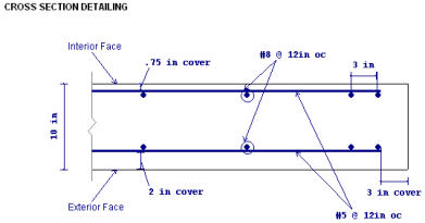
The reinforcement layout algorithm works as follows (picture looking down on a cross section of wall):
First the required spacing is calculated and the wall region length is divided by this spacing.
Note:
The axial tensile capacity for a wall assumes all reinforcement is fully developed. The capacity (with no bending interaction) equals:
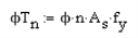
where n = number of vertical bars in the wall.
The axial compressive capacity (with no bending interaction) is taken from equation 10-2.
If CSA A23.3-14 code is selected, Clause 10.10.4 was used to calculate the axial compressive capacity (with no bending interaction).
Note:
When ACI 318-19 is selected, Vc is calculated using Equation (c) in Table 22.5.5.1. Note that ACI 318-19 code suggests ρw may be taken as the sum of the areas of longitudinal bars located more than two-thirds of the overall member depth away from the extreme compression fiber. Therefore, RISA calculates ρw as the sum of the areas of vertical bars on the tension face.
When other ACI 318 editions are selected, the equations from ACI 318-14 Sections 22.5.6.1 and 22.5.7.1 (ACI 318-11 Section 11.2.15 and 11.2.3) is used for Vc.
When CSA A23.3-14 are selected, Vc is calculated in the same way as In-Plane shear section.
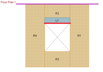
The addition of openings into a wall in the wall panel editor will automatically create a lintel above the opening. It will be symbolized by a blue bar that has the name of the lintel inside of it. The program will produce axial, shear and moment diagrams for the lintel that can be viewed from the Concrete Wall Detail Report from the Lintel drop-down option. Here we will explain some of the different considerations.
In RISAFloor the lintel forces are taken from a point that is directly at the top of opening location (see the red line below). These forces are then used to calculate the shears and moments along the length of the lintel. These analysis results are shown in the detail report.
Thus, every lintel (regardless of how regions are laid out) will give the shear and moment diagrams in the detail report.
See the Wall Panel Load Attribution topic for more information.
The program will use the Wall Design Rules and start with the maximum spacing and check that configuration for strength, spacing, and minimum reinforcing requirements. If the max spacing works, then the design is done. If not then the program will reduce the spacing by the spacing increment and then do the same checks. This will occur until a bar spacing is reached to satisfy the code requirements.
If you are using RISAFloor and RISA-3D in tandem to do gravity and lateral design, then the program envelopes the results of both. Thus, RISAFloor will never increase the spacing of bars larger than what was required in RISA-3D and vice versa. Also, when moving between programs, the reinforcement spacing that controls will be carried on into the other program.
For example, let's assume RISAFloor required vertical bars that are #6 @ 12" oc. We then use the Director to take the model to RISA-3D. In RISA-3D, the required vertical bars are #6 @ 8" oc. Now, if we take the model back to RISAFloor and solve again, the #6 @ 8" oc spacing is brought over to RISAFloor and code checks are now based on this spacing.
Note:
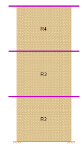
For multi-story walls that have
If you want to change bar size over the height of the wall, simply create separate wall panels and stack them on top of one another. In this way you can define different Design Rules and thus different reinforcement bar sizes up and down the wall (see Figure 2).
For the stacked regions model where the intention is to drop off bars as you work your way up the wall, lets give an example. Let's say that at the base of the wall you have bars at a 4" o.c. spacing. At some point you want to drop off bars to create an 8" o.c. spacing.
All you need to do here is set your Design Rules such that the Min Vert Bar Spacing is set to 4", the Max Vert Bar Spacing is set to 8" and the Spacing Increment is set to 4".
The program is able to consider different reinforcement cover dimensions for each face of the wall. Because of this the orientation of the wall is important. In the program the Exterior Face of the wall is oriented in the +z local axis direction. The Interior Face of the walls is oriented in the -z local axis direction.
Note:
A wall drawn in a clock-wise fashion will have its local axis pointed in the positive direction. A wall drawn in a counter-clockwise fashion will have its local axis point in the negative direction.
If the wall local axis is facing the wrong direction then use the Local Axis Flip from the Modify Walls dialog to correct it.
When bringing a model from RISAFloor to RISA-3D then you want to think about how you are drawing in RISAFloor so that the local axes come in properly in RISA-3D. You will want to draw the walls in in RISAFloor in a counter-clockwise manner to get the local z axes to point outward.
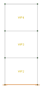
Wall Panels Drawn in RISAFloor in Counter-Clockwise Fashion
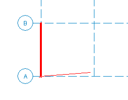
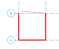
Image of Local Axes in RISA-3D
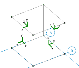
You can go to Model Display Options - Panels tab to view the local axes for the wall.